Gate valve diagram section cut through valve gate wedge parts drawing Motor operated valve schematic diagram Pneumatic circuit symbols explained |library.automationdirect
Valve Trim and Parts Including API Trim Charts
Valve globe plug diagram valves gate ball water control flow line main disc butterfly work do type svg vs plugs
Symbol for valve in schematic
Valve symbols: understanding how to read fds and p&idsValve relief pressure water heater seat tpr temperature valves Valves timing mechanism engineeringlearnButterfly valve and gate valve.
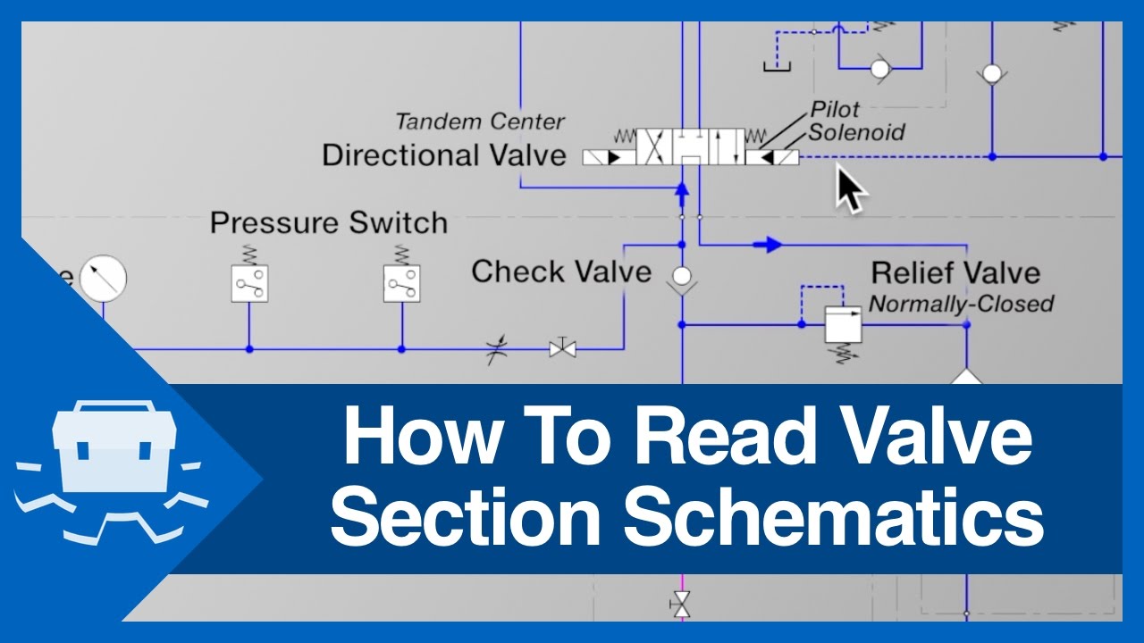
How to read valve section schematicsGlobe valve A control valve with parts and...Flow control valve circuit diagram.

Schematic illustration of the valve system
Embracing the advantages of butterfly valves – zhy castingSchematic symbol for valve Open center valve schematicPneumatic symbols circuit valve position explained solenoid spring double return flow actuated path.
[diagram] 3 way pneumatic valve diagramNeumatica, diagrama de circuito, diagrama de circuito eléctrico File:globe valve diagram-en.svgHydraulic solenoid valve wiring diagram.

Pressure relief valve schematic
Types of engine valves: valve timing diagram & valve operatingJohn curtin Valve globe valves control flow piping mechanical pipe water fitter hose engineering gate ball stem rising bib std safety stopValve trim.
Globe valvePressure regulating valve diagram Relief valve symbol schematicVelan hardhatengineer.

Pressure regulator pid symbol
Valve trim and parts including api trim chartsValve read schematics section .
.